Cisco SD-WAN 20.3.1 setup in GNS3
Updated:
In this post, we will go through all the steps of how to configure the CISCO SD-WAN lab in GNS3. This includes of two main parts:
- Setting up the Initial Topology for the control plane devices: vManage, vBond, and vSmart.
- Extend the initial lab by adding some more sites.
There are some excellent resources that I have learned a lot from when I tried to set up this lab:
- Brad Searle@codingpackets
- Alin Iorguta@poc::v:lab
- Jedadiah Casey@neckercube
1. Software/hardware requirements and initial topology
1.1. Lab Software
- GNS3 version 2.2.12
- VMware® Workstation 15 Pro
- vManage - 20.3.1
- vBond and vEdge - 20.3.1
- vSmart - 20.3.1
- vEdge - 20.3.1
1.2. Hardware requirements
I have the Dell Desktop XPS 8390 with 32GB RAM 12vCPUs and allocate 16GB RAM and 8 vCPUs for the GNS3 VM to spin up this basic SD-WAN lab. In this lab:
- vManage is 12 GB RAM, 2 vCPUs, 30 GB storage;
- vSmart is 4 GB RAM, 1 vCPU, no required storage;
- vBond is 2GB RAM, 1 vCPU, no required storage.
The other nodes:
- Border Router: CSR1000v - 3GB RAM, 1 vCPU;
- 2 vEdges router: 2 GB RAM and 1 vCPU each.
When the full lab is running the gsn3 VM CPU 28.5%; RAM 85.9%.
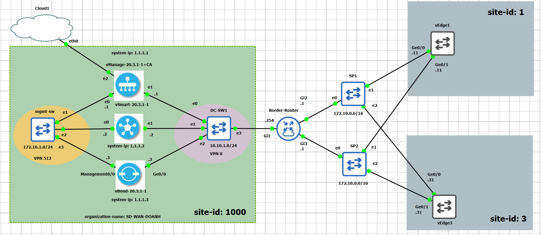
1.3. Initial Topology
The initial topology in GNS3 is as in the figure below.
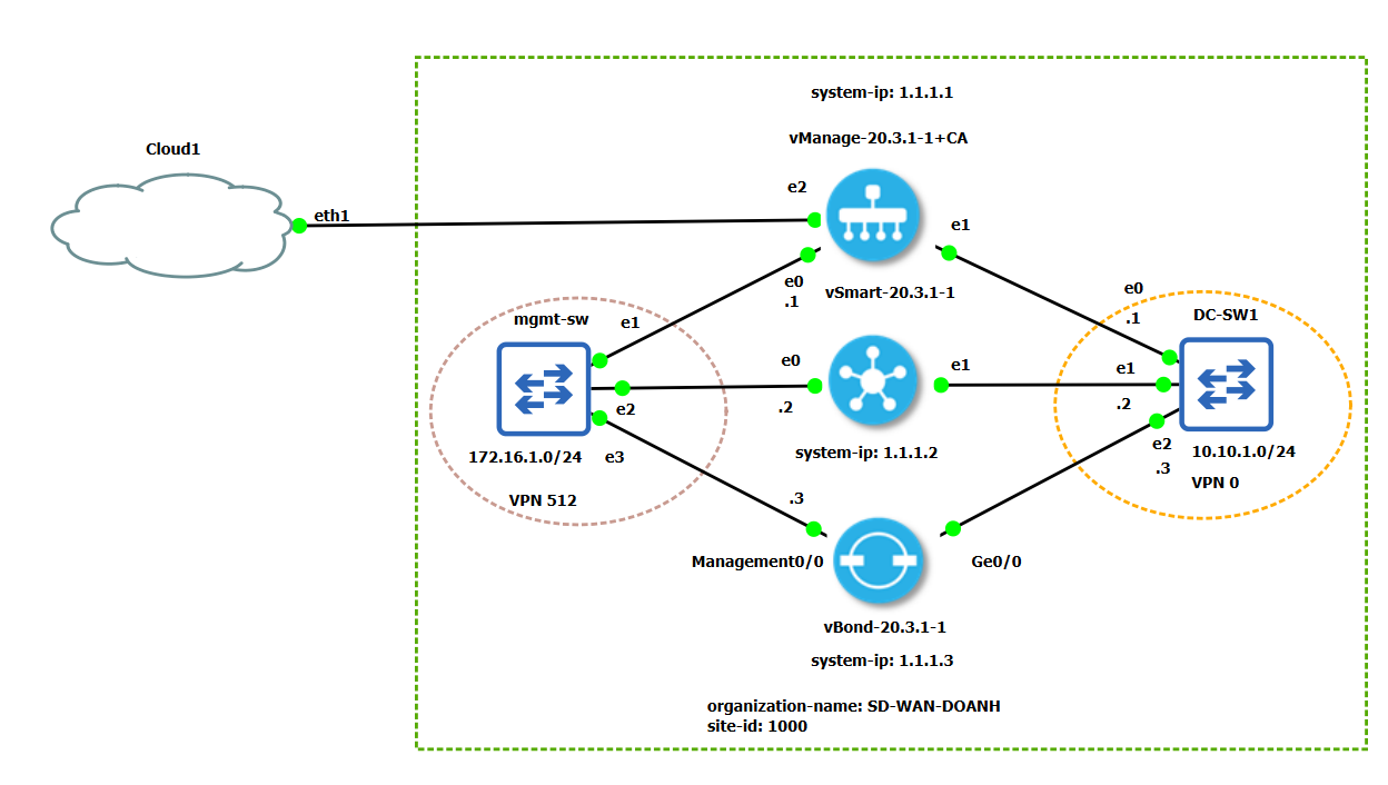
We set up the topology with the following details in mind.
- Networks in host machine, created by VMware:
- Host-only: VMnet1 - 192.168.134.0/24
- NAT: VMnet8 - 192.168.100.0/24
We need to group the interfaces into 2 different VPNs: VPN 0 for control and VPN 512 for management.
| Host | VPN 512 (mgmt) | VPN 0 (control) |
|---|---|---|
| vManage | eth0 - 172.16.1.1/24 | eth1 - 10.10.1.1/24; eth2 - 192.168.134.138/24 |
| vSmart | eth0 - 172.16.1.2/24 | eth1 - 10.10.1.2/24 |
| vBond | eth0 - 172.16.1.3/24 | Ge0/0 - 10.10.1.3/24 |
Note that, vManage has eth2 that connects it with the host machine through VMnet8, so that
we can connect to the vManage web interface using the IP address: 192.168.134.138.
1.4. Viptela CLI modes
There are two cli modes in Viptela device software: viptela-cli and vshell. When you
login to a Viptela device terminal, you are placed in the viptela-cli mode. To enter
the vshell mode, using the command vshell, and exit to return back to viptela-cli
mode.
vmanage# vshell
vmanage:~$ exit
exit
vmanage#
You can find the best sdwan command cheatsheet here.
2. Control plane devices configuration
In this lab, we will start by configuring the root CA. The root CA is configured in the vManage device to simplify the topology. Next we move onto installing certificate on each Viptela device, including vManage, vBond, vSmart.
2.1. vManage
Boostrap configuration
We need to spin up vManage in GNS3. During this step, we can set up the user and password to
log into vManage (admin/admin) and configure the boostrap configuration in configuration mode
conf t.
system
 host-name             vmanage
 system-ip             1.1.1.1
 site-id               1000
 admin-tech-on-failure
 sp-organization-name  SD-WAN-DOANH
 organization-name     SD-WAN-DOANH
 vbond 10.10.1.3
vpn 0
 interface eth1
  ip address 10.10.1.1/24
  tunnel-interface
  !
  no shutdown
 !
 interface eth2
  ip dhcp-client
  no shutdown
 !
 ip route 0.0.0.0/0 10.10.1.254
!
vpn 512
 interface eth0
  ip address 172.16.1.1/24
  no shutdown
 !
!
Note that, IP address of eth2 is assigned by the DHCP server of VMnet8. To check using
sh int | tab.
Now, we can access the vManage web interface with a web browser at https://192.168.134.138:8444/.
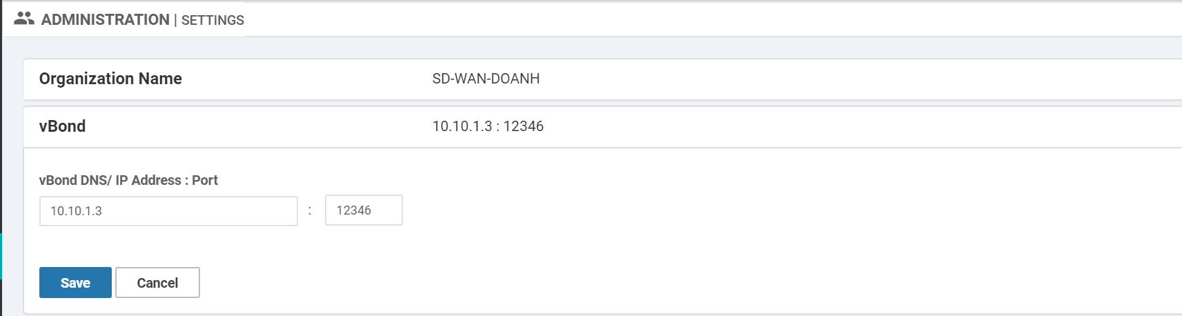
Then we need to set the Organization name and vBond IP address in vManage Web Interface.
Going to Administration > Settings and set the organization name and vBond as in the figure
below.
Configure root CA in vManage
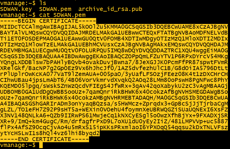
To configure the Certificate Authority in vManage, generate key and certificate. In vManage
vshell mode:
openssl genrsa -out SDWAN.key 2048
openssl req -x509 -new -nodes -key SDWAN.key -sha256 -days 2000 \
        -subj "/C=UK/ST=LD/L=LD/O=SD-WAN-DOANH/CN=SD-WAN" \
        -out SDWAN.pem
ls
cat SDWAN.pem
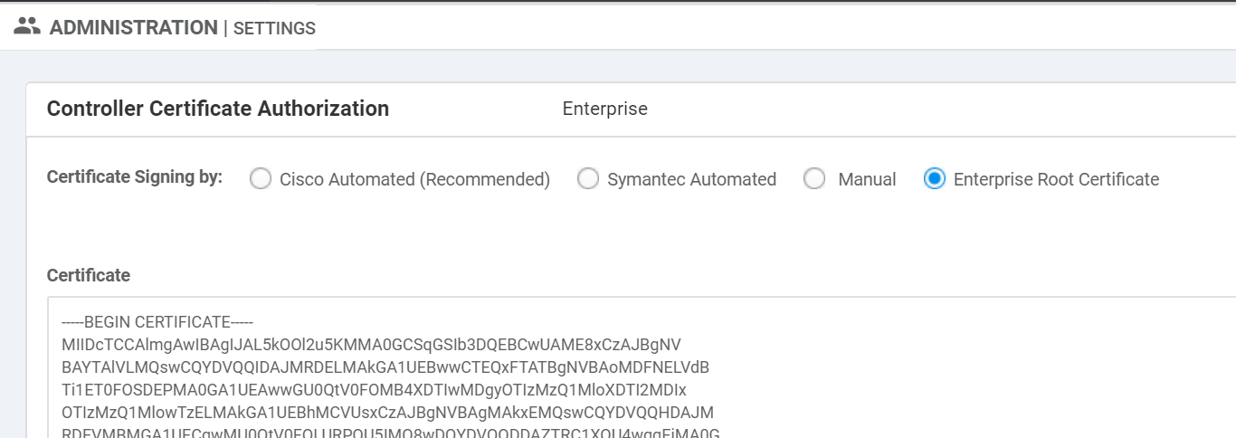
Copy SDWAN.pem content to Administration > Settings > Controller Certification
Authorization > Enterprise Root Certificate.
From the browser, go to
https://192.168.134.138/dataservice/system/device/sync/rootcertchain to request a
resync of the vManage database via API call. The answer in JSON format
should be: {"syncRootCertChain":"done"}.
Install the certificate
We need to create Certificate Signing Request (CSR) in vManage Web interface:
Configuration > Certificates > Controllers > Generate CSR.
Copy the CSR content, go back to vManage vshell mode, create an empty file vManage.csr with
vim vManage.csr, then paste the copied content to this file, save it.
Sign the vManage.csr with the CA certificate and key using openssl:
openssl x509 -req -in vManage.csr -CA SDWAN.pem -CAkey SDWAN.key -CAcreateserial -out vManage.crt -days 2000 -sha256
ls
cat vManage.crt
Copy the content of vManage.crt and install the certificate at vManage web interface
Configuration > Certificates > Controllers > Select vManage > Install Certificate.
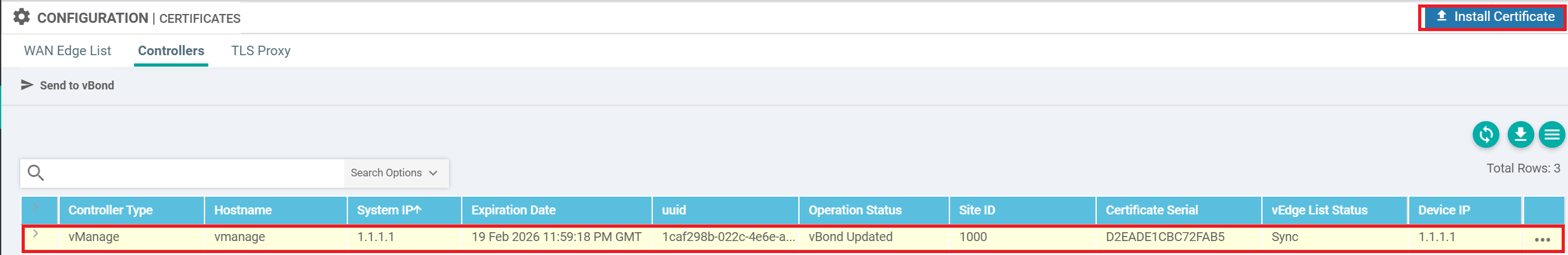
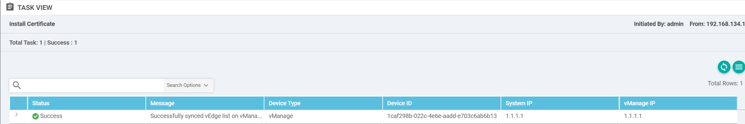
Successful certificate install log:
2.2. Adding vBond controller
Boostrap configuration
First, we spin up vBond in GNS3. During this step, we can set up the user and password to
log into vBond (admin/admin) and configure the boostrap configuration in configuration mode
conf t.
system
 host-name               vbond
 system-ip               1.1.1.3
 site-id                 1000
 admin-tech-on-failure
 no route-consistency-check
 organization-name       SD-WAN-DOANH
 vbond 10.10.1.3 local vbond-only
vpn 0
 interface ge0/0
  ip address 10.10.1.3/24
  ipv6 dhcp-client
  tunnel-interface
   encapsulation ipsec
  !
  no shutdown
 !
 ip route 0.0.0.0/0 10.10.1.254
!
vpn 512
 interface eth0
  ip address 172.16.1.3/24
  no shutdown
 !
!
Install the certificate
Now, we need to copy the SDWAN.pem and SDWAN.key from vManage to vBond and use them to authenticate
vBond with vManage. Go to vManage vshell mode, use cat SDWAN.pem and cat SDWAN.key, then
copy the content of these two files.
In vBond vshell mode, paste the content of SDWAN.pem and SDWAN.key from vManage in the two
empty files SDWAN.pem and SDWAN.key with vim command.
vim SDWAN.pem
vim SDWAN.key
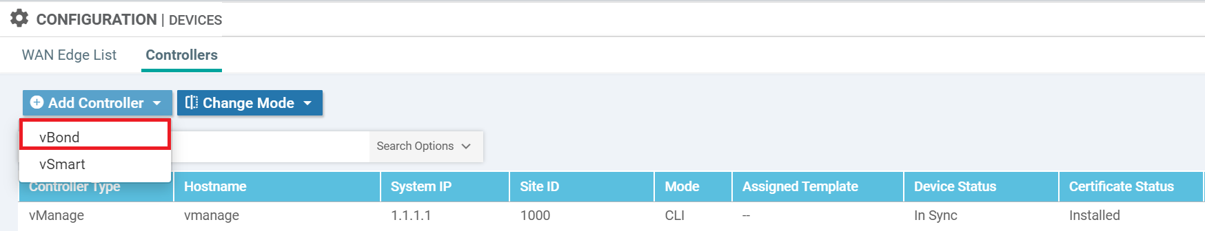
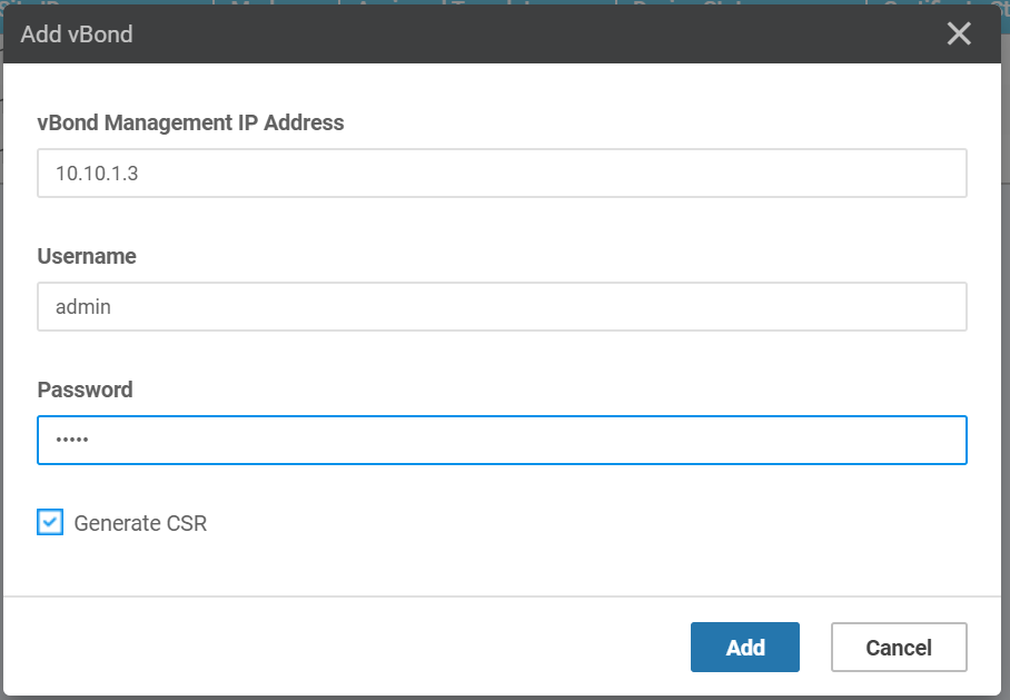
Now, we need to add the vBond controller in vManage web interface
Configuration > Devices > Controllers > Add Controller.
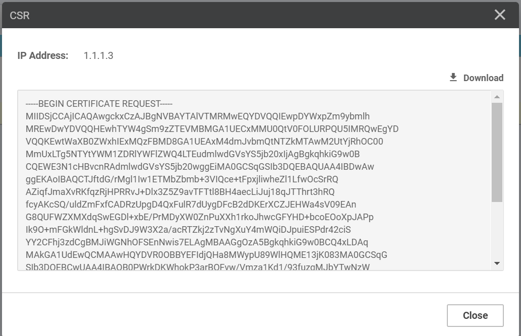
View the CSR at Configuration > Certificates > Controller > vBond > View CSR
- Copy the content of the CSR
- Go back to vBond
vshellmode and paste to the new empty file vBond.csr withvim vBonds.csr
Sign vBond.csr using openssl and generate vBond.crt
openssl x509 -req -in vBond.csr -CA SDWAN.pem -CAkey SDWAN.key -CAcreateserial -out vBond.crt -days 2000 -sha256
cat vBond.crt
Copy the content of vBond.crt and install the certificate at vManage web interface
Configuration > Certificates > Controllers > Select vBond > Install Certificate.
2.3. Adding vSmart controller
Boostrap configuration
system
 host-name             vsmart
 system-ip             1.1.1.2
 site-id               1000
 admin-tech-on-failure
 organization-name     SD-WAN-DOANH
 vbond 10.10.1.3
vpn 0
 interface eth1
  ip address 10.10.1.2/24
  tunnel-interface
  !
  no shutdown
 !
 ip route 0.0.0.0/0 10.10.1.254
!
vpn 512
 interface eth0
  ip address 172.16.1.2/24
  no shutdown
 !
!
Install the certificate
In vSmart vshell mode, paste the content of SDWAN.pem and SDWAN.key from vManage
vim SDWAN.pem
vim SDWAN.key
Add the vSmart controller in vManage web interface at
Configuration > Devices > Controllers > Add Controller.
View the CSR at Configuration > Certificates > Controller > vSmart > View CSR
- Copy the content of the CSR
- Go back to vSmart
vshellmode and paste to vSmart.csr
Sign vSmart.csr using openssl and generate vSmart.crt
openssl x509 -req -in vSmart.csr -CA SDWAN.pem -CAkey SDWAN.key -CAcreateserial -out vSmart.crt -days 2000 -sha256
cat vSmart.crt
Copy the content of vSmart.crt and install the certificate at vManage web interface
Configuration > Certificates > Controllers > Select vSmart > Install Certificate.
3. Extend initial topology with more sites
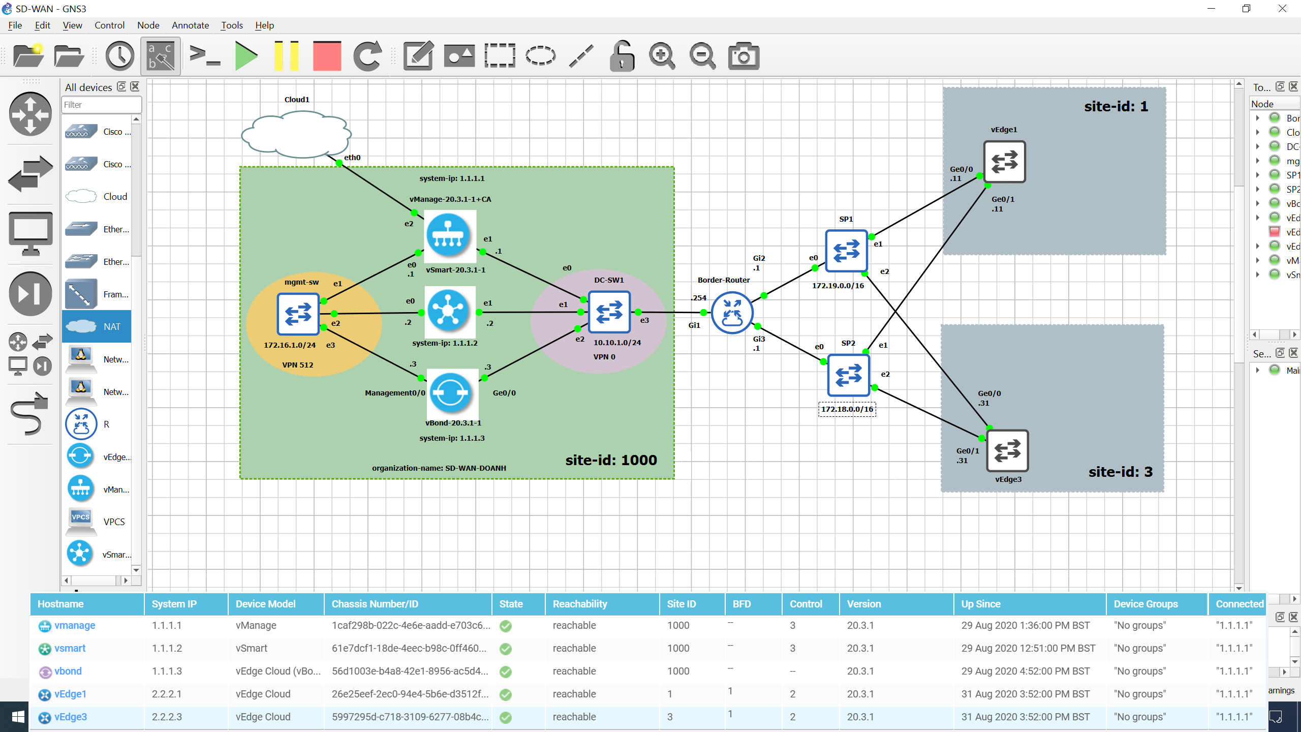
3.1. Extend topology
The extended topology is as in the following figure.
3.2. Adding Border Router
hostname R1
interface GigabitEthernet1
 ip address 10.10.1.254 255.255.255.0
 no shutdown
!
interface GigabitEthernet2
 ip address 172.19.0.1 255.255.0.0
 no shutdown
!
interface GigabitEthernet3
 ip address 172.18.0.1 255.255.0.0
 no shutdown
!
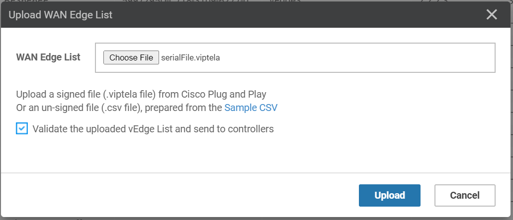
3.3. Upload the WAN Edge list
At this step, we will need an valid WAN Edge List. You can go to the poc::v:lab site for more information of how to get this list.
Go to Configuration > Devices and click Upload WAN Edge List.
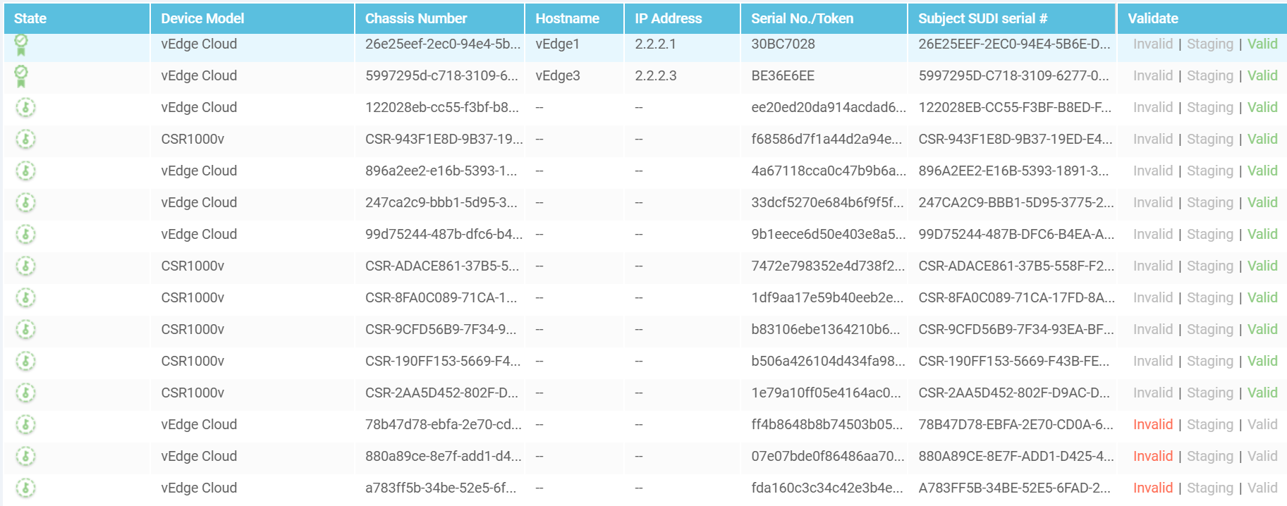
After uploading the WAN Edge List, you’ll see your devices in Configuration > Devices.
You will need to valid the edge device by going to Configuration > Certifcates > WAN Edge List
and click valid under the Validate column.
3.4. Adding vEdge1 node
Bootstrap configuration
We will add vEdge1 of site-id 1 to the topology. The boostrap configuration is as follows:
system
 host-name               vEdge1
 system-ip               2.2.2.1
 site-id                 1
 admin-tech-on-failure
 no route-consistency-check
 organization-name       SD-WAN-DOANH
 vbond 10.10.1.3
vpn 0
 interface ge0/0
  ip address 172.19.0.11/16
  ipv6 dhcp-client
  tunnel-interface
   encapsulation ipsec
  !
  no shutdown
 !
 interface ge0/1
  ip address 172.18.0.11/16
  no shutdown
 !
 ip route 0.0.0.0/0 172.19.0.1
!
Install the certificate
We will need to copy the content of SDWAN.pem from vManage to vEdge1. In vEdge1,
go to vshell mode, create an empty file with vim SDWAN.pem, then paste the copied content,
exit to return back to the viptela-cli mode.
vEdge1# vshell
vEdge1:~$ vim SDWAN.pem
vEdge1:~$ exit
vEdge1#
Now, we can import the certificate.
request root-cert-chain install /home/admin/SDWAN.pem
Go to vManage interface, Configuration > Devices > Select unused entry > ... > Generate Bootstrap
Configuration, to see the boostrap information, what we need is the UUID and token to be used
in the next command. Note that, since we use vEdge, the unused entry we select needs to
be of model vEdge Cloud.
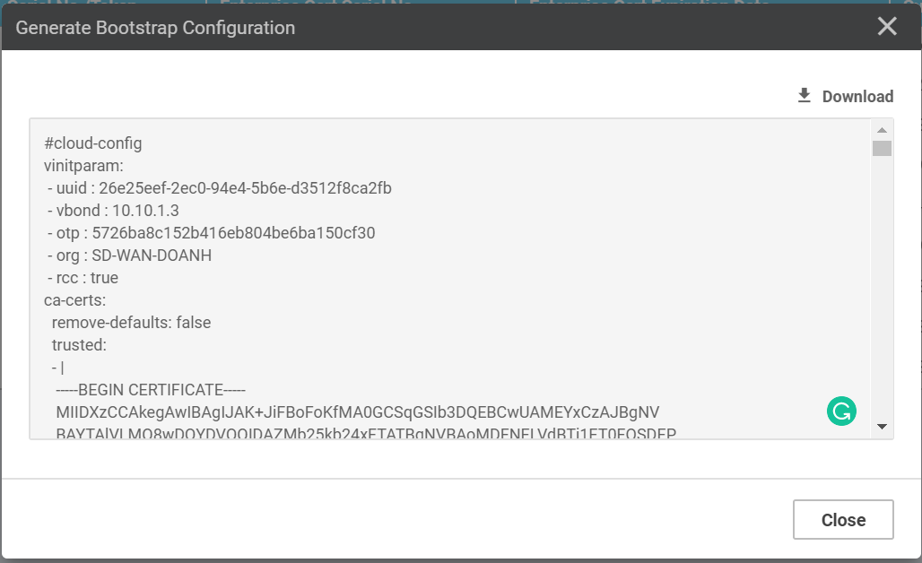
request vedge-cloud activate chassis-number uuid token otp
One example is as follows:
request vedge-cloud activate chassis-number 26e25eef-2ec0-94e4-5b6e-d3512f8ca2fb token 5726ba8c152b416eb804be6ba150cf30
Check with show control local-properties.
3.5. Adding vEdge3 node
Boostrap configuration
system
 host-name               vEdge3
 system-ip               2.2.2.3
 site-id                 3
 admin-tech-on-failure
 no route-consistency-check
 organization-name       SD-WAN-DOANH
 vbond 10.10.1.3
vpn 0
 interface ge0/0
  ip address 172.19.0.31/16
  ipv6 dhcp-client
  tunnel-interface
   encapsulation ipsec
  !
  no shutdown
 !
 interface ge0/1
  ip address 172.18.0.31/16
  no shutdown
 !
 ip route 0.0.0.0/0 172.19.0.1
!
vpn 512
 interface eth0
  ip dhcp-client
  ipv6 dhcp-client
  no shutdown
 !
!
Install the certificate
Repeat the same process as with vEdge1:
request root-cert-chain install /home/admin/SDWAN.pem
request vedge-cloud activate chassis-number 5997295d-c718-3109-6277-08b4caea2bcf token 764fa250066c4e90bb994ce60994bf90
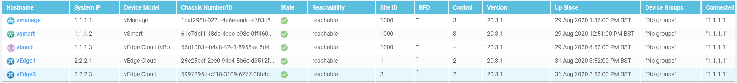
Verify by going to Monitor > Network, note that there are two more vEdges that have been
recognized by vManage.
4. Conclusion
In this lab, we went through all the steps to configure the basic SD-WAN in GNS3. Now, everything is up and running. Let’s grab an SD-WAN book, study hard, and check the knowledge with this lab.
Comments