Cisco SD-WAN: Configuring and Attaching Templates to WAN Edge devices for BGP configuration
Updated:
I recently joined a study group at RouterGods, focusing on Cisco SD-WAN solutions. Let me start first by saying thank you to my RouterGods friend Judson Bishop for organizing this study group. I also want to say thank to Tim at Carpe DMVPN, Ryan, and Cedric for sharing their knowledge and making the discussion very productive, fun and much easier to understand the complex concepts.
When learning about a new technology:
- Khawar Butt: “see it, touch it to believe it”.
- Judson’s friend : “build it, break it, fix it to learn it”.
Inspiring by these spirits, Judson has built a full-topology lab from the SD-WAN book in EVE-NG to learn based on practising with the lab. At the time we started the group, my computer was not powerful enough to run the full-topology in EVE-NG, so I rebuilt it in GNS3 (GNS3 has a way to limit the CPU and RAM resources for each appliance in the topology). My task was easy since Judson has done all heavy tasks such as designing the IP addressing scheme, setting up initial configurations.
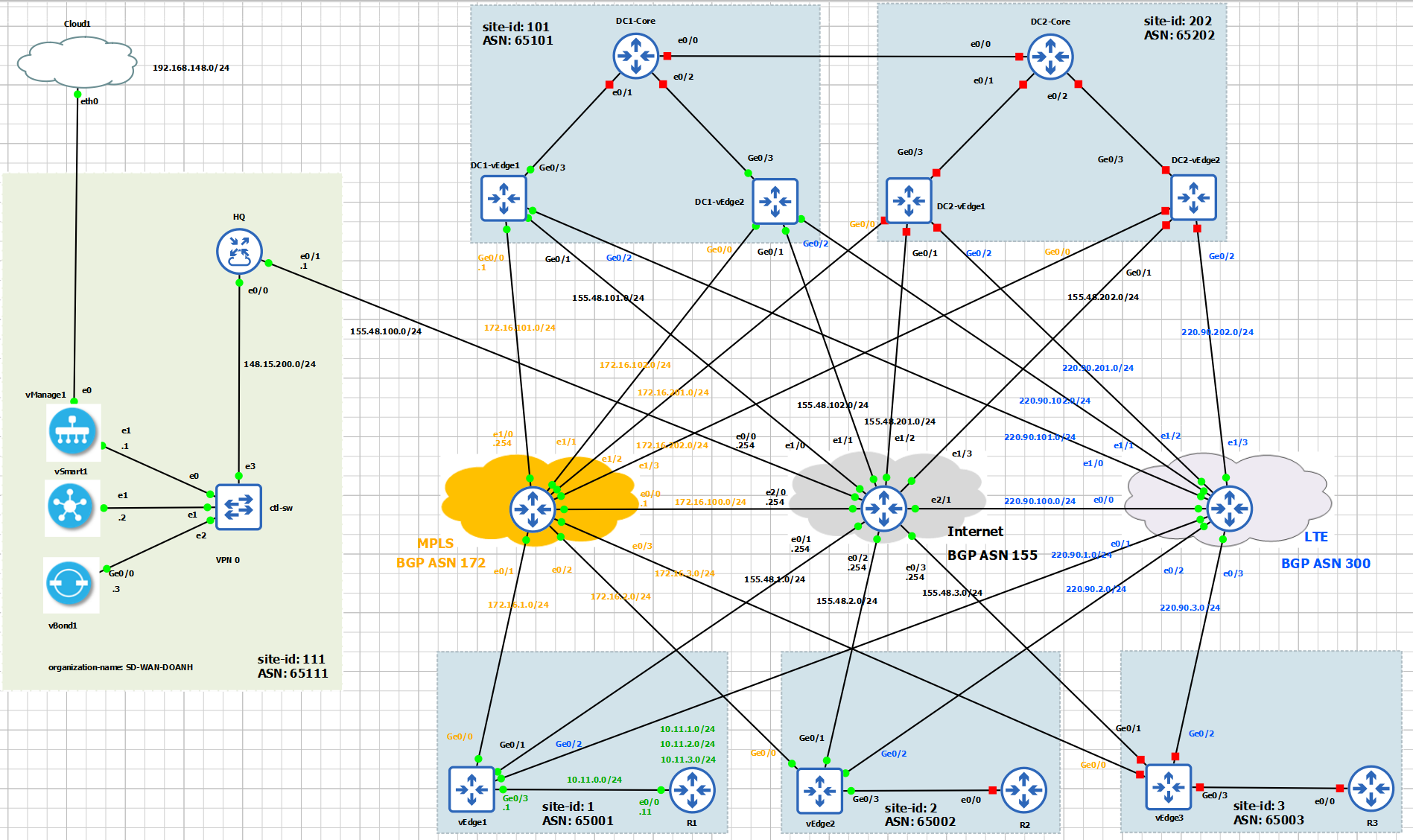
And here is the topology in GNS3:
I have heard a lot about the power of SD-WAN: the way we can create Device and Feature templates from vManage GUI and applying a device template to a single device or multiple devices to push configuration to WAN Edge routers. All are very fantastic!!! However, as a beginner, I don’t know what a feature template or a device template is. I struggled to get my head around how to construct a device template, what are the required components, and how do we utilise them?
I highly recommend reading/watching the following top-notch resources from Tim that answer all the above questions.
Feature template is the building block of configuration for a specific technology feature that we want to enable or config, such as routing protocols (OSPF, BGP), interface parameters.
Device templates are a collection of feature templates and can be attached to the devices.
My purpose for this post is:
- to build the device template for configuration of
vEdge1,vEdge2, andDC1-vEdge1in the full-topology lab in GNS3, including System, banner, interfaces, and BGP configurations. - I will also take a further step to modify some feature templates (VPN Interface Ethernet templates), to include
the
restrictattribute andtunnel groupsoptions, to control the data plane connectivity among WAN Edge routers.
Let’s take a close look at vEdge1.
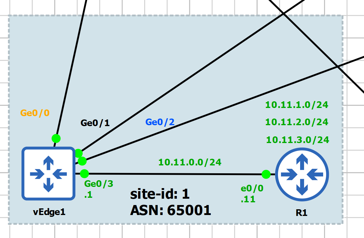
What we need for vEdge1:
- Transport VPN: VPN0, configuration for
Ge0/0,Ge0/1,Ge0/2 - Service VPN: VPN1, configuration for
Ge0/3 - Management VPN: VPN512, configuration for
eth0 - BGP neighbor with Internet via
Ge0/1and BGP neighbor with LTE via ‘Ge0/2’
Let’s start building piece-by-piece the necessary feature templates:
- Create system template
- Create banner template (optional)
- Create VPN templates: VPN0, VPN1, VPN512
- Create VPN Interface templates: VPNINT-VPN0-G0, G1, G2; VPNINT-VPN1-G3, VPNINT-VPN512-E0
- Create BGP template
1. Create Feature Template
Before starting create template, it is very important to plan the template name properly. We need to come up with a meaningful way to name the template that is suitable for the intent use of the template. For example, let’s us consider the following naming convention:
- System template for vEdge Cloud at a Branch: BR-VE-SYSTEM
- VPN template for vEdge Cloud at a Branch: BR-VE-VPN-VPN0
When we create a template, for each parameter we have three types of settings as follows:
- Global: Apply to all devices using this template, will not be asked for this parameter when the template is attached to a device.
- Device specific: when apply template, we will need to specify this parameter.
- Default: Factory default value.
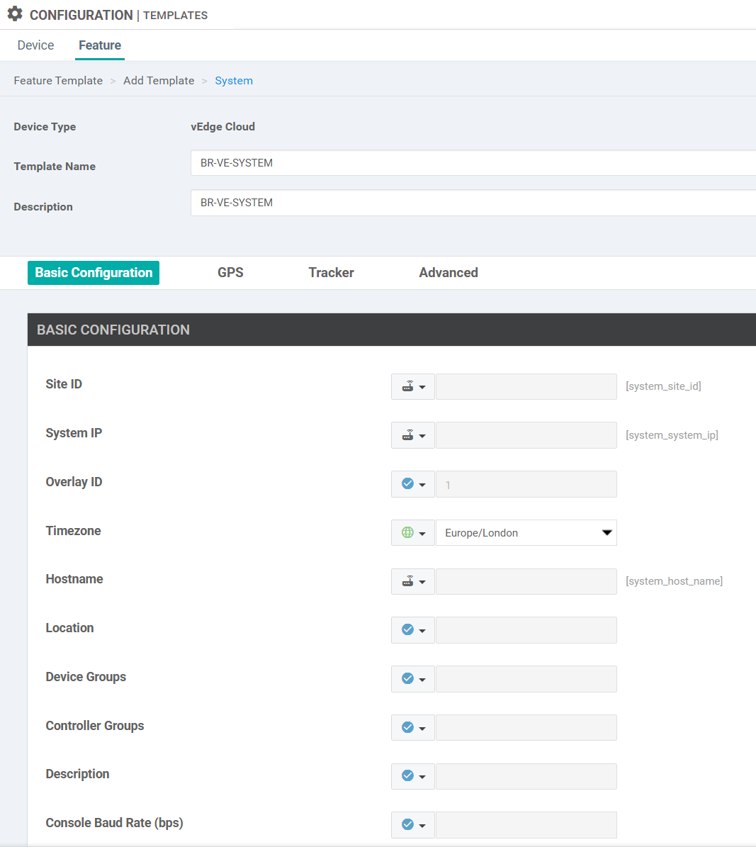
1.1. Create System Template
This template is used for the Branch WAN Edge router, the type of the router is vEdge Cloud, and contains the system information.
- Template Name: BR-VE-SYSTEM
- Site ID: Device Specific
- System IP: Device Specific
- Hostname: Device Specific
- Timezone: Global: Europe/London
- Console Baud Rate: Default
We create the first BR-VE-SYSTEM template as in the following figure.
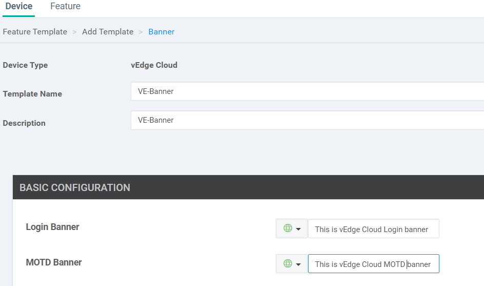
1.2. Create Banner Template (Optional)
- Template name: VE-banner
- Description: VE-banner
- Login banner: Global “This is vEdge Cloud Login banner”
- MOTD banner: Global “This is vEdge Cloud MOTD banner”
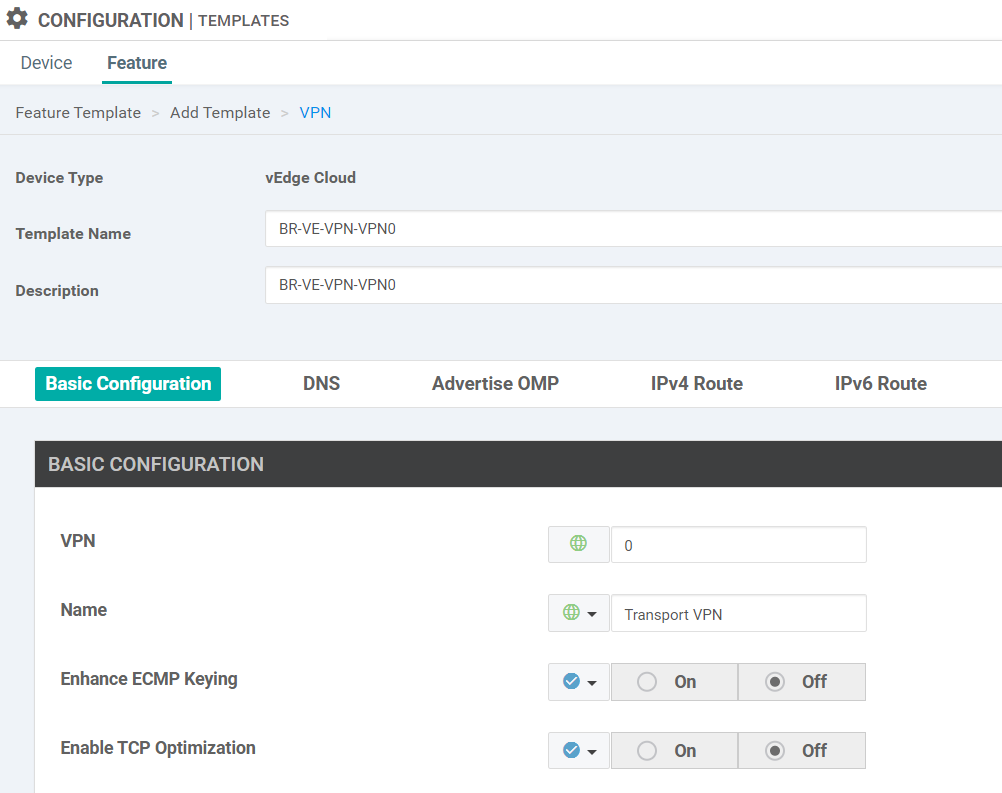
1.3. Create VPN Templates
Create VPN0 Template
- Template Name: BR-VE-VPN-VPN0
- Description: BR-VE-VPN-VPN0
- Basic configuration:
- VPN: Global: 0
- Name: Global: Transport VPN
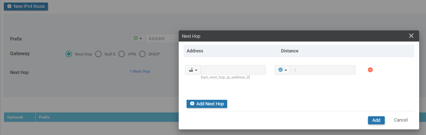
- IPv4 Route Configuration:
- Prefix: Global: Default
- Next Hop: Device Specific
- Key Value: vpn0_next_hop_ip_address_0
Create VPN1 Template
- Template Name: BR-VE-VPN-VPN1
- Description: BR-VE-VPN-VPN1
- Basic configuration:
- VPN: Global: 1
- Name: Global: Service VPN
Create VPN512 Template
- Template Name: BR-VE-VPN-VPN512
- Description: BR-VE-VPN-VPN512
- Basic configuration:
- VPN: Global: 512
- Name: Global: Management VPN
1.4. Create VPN Interface Ethernet Templates
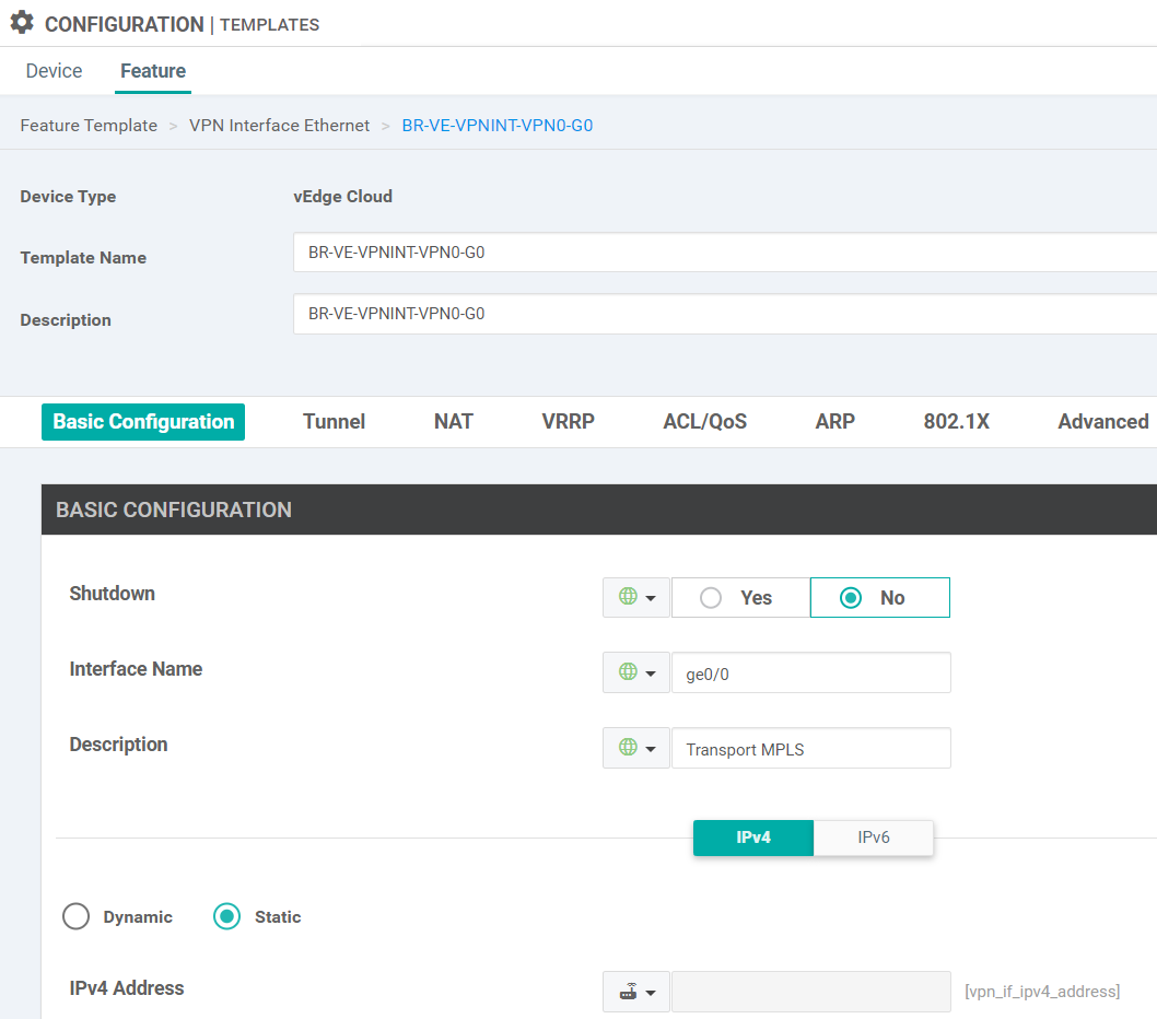
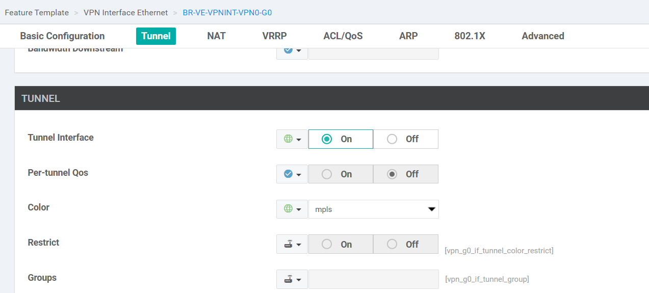
Create BR-VE-VPNINT-VPN0-G0
- Template Name: BR-VE-VPNINT-VPN0-G0
- Description: BR-VE-VPNINT-VPN0-G0
- Basic Configuration
- Shutdown: Global: No
- Interface Name: Global: ge0/0
- Description: Global: Transport MPLS
- IPv4 Address:
- Static: Device Specific
- Key Value: vpn_g0_if_ipv4_address
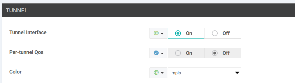
- Tunnel
- Tunnel Interface: Global: On
- Color: Global: mpls
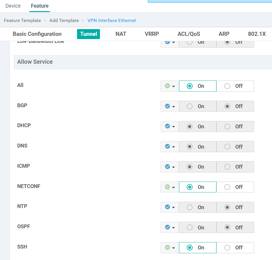
- Allow Service
- All: Global: On
- NETCONF: Global: On
- SSH: Global: On
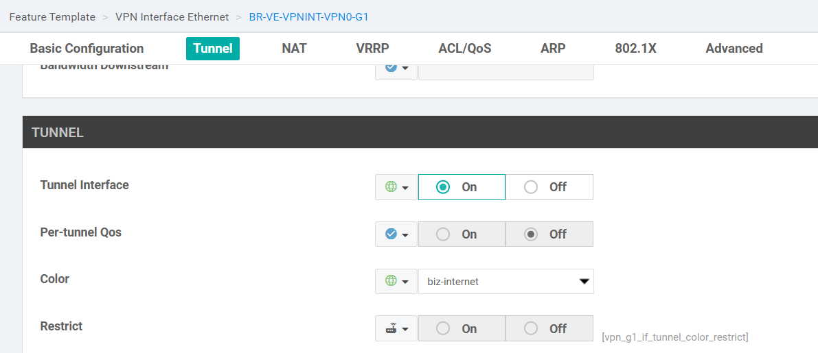
Create BR-VE-VPNINT-VPN0-G1
Copy from BR-VE-VPNINT-VPN0-G0, only change the following fields:
- Interface name: ‘ge0/1’
- Description:
Transport Internet - Select color as
biz-internet
Create BR-VE-VPNINT-VPN0-G2
Copy from BR-VE-VPNINT-VPN0-G0, only change the following fields:
- Interface name: ‘ge0/2’
- Description:
Transport LTE - Select color as
lte
Create BR-VE-VPNINT-VPN1-G3
- Template Name: BR-VE-VPNINT-VPN1-G3
- Description: BR-VE-VPNINT-VPN1-G3
- Basic Configuration
- Shutdown: Global: No
- Interface Name: Global: ge0/3
- Description: Global: Service VPN1 Interface
- IPv4 Address:
- Static: Device Specific
- Key Value: vpn_g3_if_ipv4_address
Create BR-VE-VPNINT-VPN512-ETH0
- Template name: BR-VE-VPNINT-VPN512-ETH0
- Description: BR-VE-VPNINT-VPN512-ETH0
- Interface name: Global eth0
- IPv4: Dynamic
1.5. Create Routing Feature Templates
Create OSPF Template
- Template name: BR-VE-OSPF-VPN0
- Description: BR-VE-OSPF-VPN0
- Router ID: Default
- Area number: Global: 0
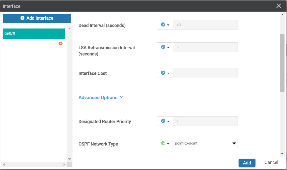
- Add interface:
- Interface name: Global ge0/0
- Advanced options: OSPF network type: Global point-to-point
Create BGP Template
BR-VE-BGP-VPN0
- Template Name: BR-VE-BGP-VPN0
- Basic Configuration
- Shutdown: Global: No
- AS Number: Device Specific
- Key Value: bgp_local_as_num
- Adding Neighbor to LTE transport
- Address: Device Specific
- Key Value: bgp_lte_neighbor_address
- Remote AS: Global: 300
- Address Family: Global: On
- Address Family: Global: IPv4-Unicast
- Adding Neighbor to biz-internet transport
- Address: Device Specific
- Key Value: bgp_biz_neighbor_address
- Remote AS: Global: 155
- Address Family: Global: On
- Address Family: Global: IPv4-Unicast
2. Create Device Template
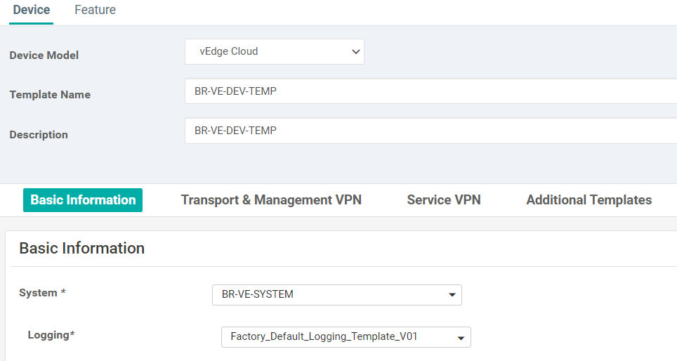
2.1. BR-VE-DEV-TEMP
- Template Name: BR-VE-DEV-TEMP
- Description: BR-VE-DEV-TEMP
- Basic Information
- System: BR-VE-SYSTEM
- Transport and Management VPN
- VPN 0: BR-VE-VPN-VPN0
- BGP: BR-VE-BGP-VPN0
- OSPF: BR-VE-OSPF-VPN0
- VPN Interface:
- BR-VE-VPNINT-VPN0-G0
- BR-VE-VPNINT-VPN0-G1
- BR-VE-VPNINT-VPN0-G2
- VPN 512: BR-VE-VPN-VPN512
- VPN Interface:
- BR-VE-VPNINT-VPN512-ETH0
- VPN Interface:
- VPN 0: BR-VE-VPN-VPN0
- Service VPN
- VPN 1: BR-VE-VPN-VPN1
- VPN Interface: BR-VE-VPNINT-VPN1-G3
- VPN 1: BR-VE-VPN-VPN1
- Additional Templates:
- Banner: VE-Banner
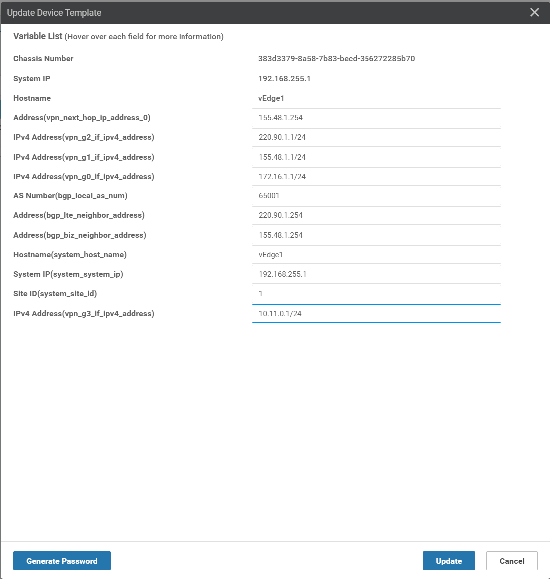
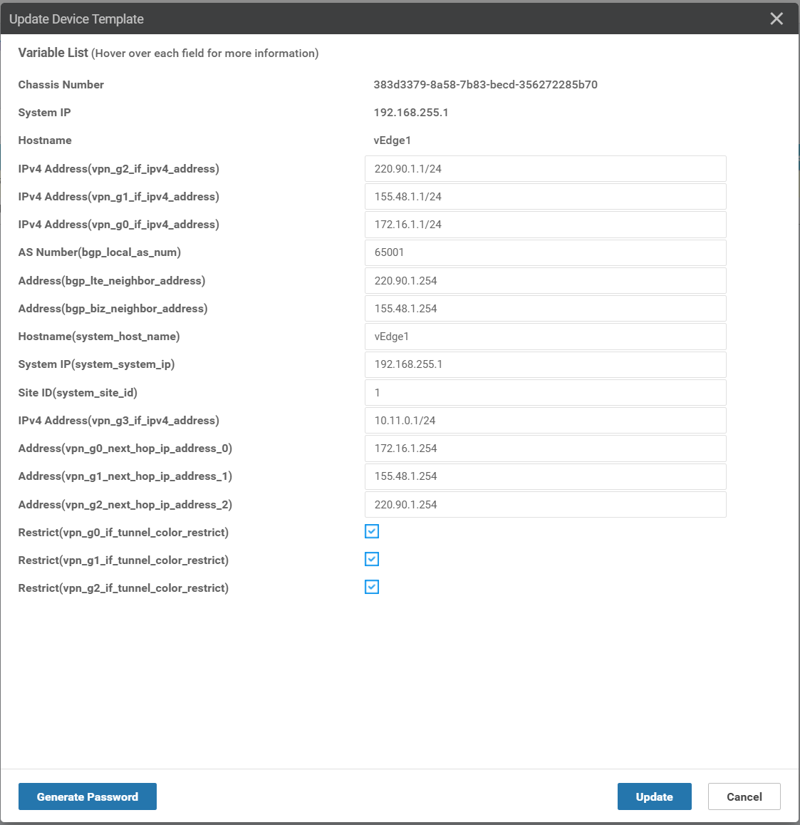
2.2. Attach device template to WAN Edges
-
Use the addressing scheme in the topology to fill in the variables when apply the device template.
-
Attach vEdge1
- Attach vEdge2
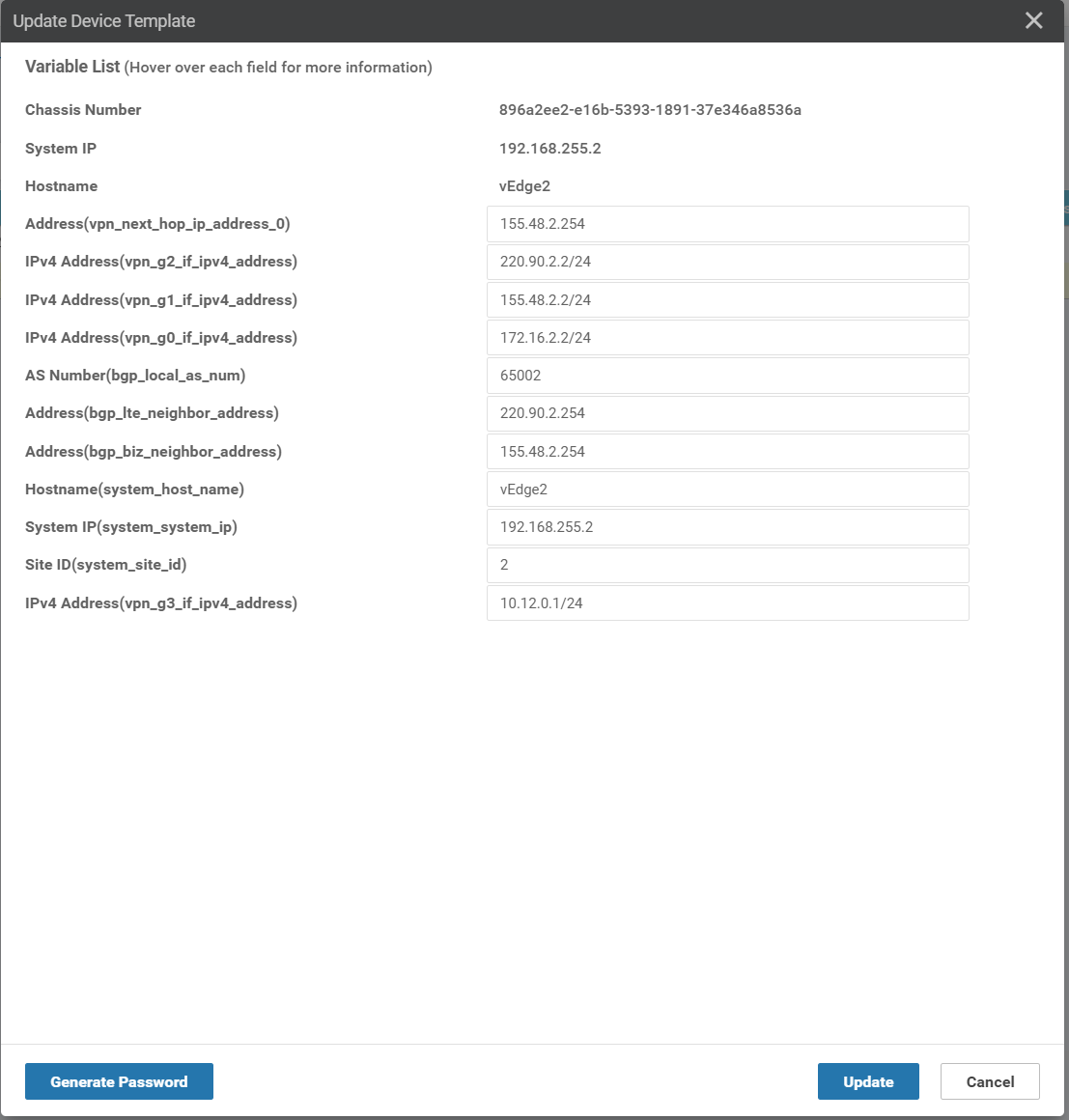
- Check the BGP configuration on
vEdge1
vEdge1# sh bgp summary
vpn                    0
bgp-router-identifier  192.168.255.1
local-as               65001
rib-entries            49
rib-memory             5488
total-peers            2
peer-memory            9632
Local-soo              SoO:0:1
ignore-soo
                       MSG       MSG       OUT                     PREFIX  PREFIX  PREFIX
NEIGHBOR         AS    RCVD      SENT      Q      UPTIME           RCVD    VALID   INSTALLED  STATE
---------------------------------------------------------------------------------------------------------
155.48.1.254     155   100       89        0      0:01:23:56       25      25      18         established
220.90.1.254     300   98        89        0      0:01:23:53       25      25      7          established
- Check the BGP configuration on
vEdge2
vEdge2# sh bgp summary
vpn                    0
bgp-router-identifier  192.168.255.2
local-as               65002
rib-entries            49
rib-memory             5488
total-peers            2
peer-memory            9632
Local-soo              SoO:0:2
ignore-soo
                       MSG       MSG       OUT                     PREFIX  PREFIX  PREFIX
NEIGHBOR         AS    RCVD      SENT      Q      UPTIME           RCVD    VALID   INSTALLED  STATE
---------------------------------------------------------------------------------------------------------
155.48.2.254     155   11        10        0      0:00:06:52       25      25      18         established
220.90.2.254     300   11        12        0      0:00:06:42       25      25      7          established
- Check the OMP routes
vEdge1# sh omp routes 10.12.0.0/24

---------------------------------------------------
omp route entries for vpn 1 route 10.12.0.0/24
---------------------------------------------------
            RECEIVED FROM:
peer            192.168.255.112
path-id         1
label           1003
status          C,I,R
loss-reason     not set
lost-to-peer    not set
lost-to-path-id not set
    Attributes:
     originator       192.168.255.2
     type             installed
     tloc             192.168.255.2, biz-internet, ipsec
     ultimate-tloc    not set
     domain-id        not set
     overlay-id        1
     site-id          2
     preference       not set
     tag              not set
     origin-proto     connected
     origin-metric    0
     as-path          not set
     community        not set
     unknown-attr-len not set
3. Control BFD connection among WAN Edge routers
3.1. Full-mesh connectivity
There are private and public colors.
- Public colors: 3g, biz-internet, public-internet, lte, blue, bronze, custom1, custom2, custom3, gold, green, red, silver. Use when there is a NAT between WAN Edge devices
- Private colors: metro-ethernet, mpls, private1 to private6. Only use when there is no NAT between devices (overlay).
When establishing the IPsec data plane, a full-mesh connectivity between all routers in the fabric is established by default.
Consider vEdge1 with 3 colors: mpls, biz-internet, lte:
vEdge1# show omp tlocs advertised | b ADD
ADDRESS
FAMILY   TLOC IP          COLOR            ENCAP
--------------------------------------------------
ipv4     192.168.255.1    mpls             ipsec
         192.168.255.1    biz-internet     ipsec
         192.168.255.1    lte              ipsec
Consider vEdge2 with 3 colors: mpls, biz-internet, lte:
vEdge2# show omp tlocs advertised | b ADD
ADDRESS
FAMILY   TLOC IP          COLOR            ENCAP
--------------------------------------------------
ipv4     192.168.255.2    mpls             ipsec
         192.168.255.2    biz-internet     ipsec
         192.168.255.2    lte              ipsec
Let’s see the BFD connections between vEdge1 (3 colors: mpls, biz-internet, lte) and vEdge2 (3 colors: mpls, biz-internet, lte). Each vEdge has three colors, so with full-mesh connectivity we have 3*3 = 9 BFD connections.
vEdge1# show bfd sessions
                                      SOURCE TLOC      REMOTE TLOC                                      DST PUBLIC                      DST PUBLIC         DETECT      TX
SYSTEM IP        SITE ID  STATE       COLOR            COLOR            SOURCE IP                       IP                              PORT        ENCAP  MULTIPLIER  INTERVAL(msec) UPTIME          TRANSITIONS
-------------------------------------------------------------------------------------------------------------------------------------------------------------------------------------------------------------
192.168.255.2    2        up          biz-internet     biz-internet     155.48.1.1                      155.48.2.2                      12346       ipsec  7           1000           0:00:38:06      0
192.168.255.2    2        up          biz-internet     mpls             155.48.1.1                      172.16.2.2                      12426       ipsec  7           1000           0:00:01:00      0
192.168.255.2    2        up          biz-internet     lte              155.48.1.1                      220.90.2.2                      12426       ipsec  7           1000           0:00:01:00      0
192.168.255.2    2        up          mpls             biz-internet     172.16.1.1                      155.48.2.2                      12346       ipsec  7           1000           0:00:00:58      0
192.168.255.2    2        up          mpls             mpls             172.16.1.1                      172.16.2.2                      12426       ipsec  7           1000           0:00:00:58      0
192.168.255.2    2        up          mpls             lte              172.16.1.1                      220.90.2.2                      12426       ipsec  7           1000           0:00:00:58      0
192.168.255.2    2        up          lte              biz-internet     220.90.1.1                      155.48.2.2                      12346       ipsec  7           1000           0:00:00:58      0
192.168.255.2    2        up          lte              mpls             220.90.1.1                      172.16.2.2                      12426       ipsec  7           1000           0:00:00:58      0
192.168.255.2    2        up          lte              lte              220.90.1.1                      220.90.2.2                      12426       ipsec  7           1000           0:00:00:58      0
To control the data plane connectivity (BFD connections), we can set the restrict attribute or configure tunnel
groups.
3.1. Control BFD connections with Restrict Attribute
The restrict attribute needs to be defined per site and can be 1 or 0.
- restrict = 1: this device will only form the tunnels with other TLOCs advertising the color
- retrict = 0: can form tunnels with other colors
To set the restrict attribute of a color, we have to configure the VPN Interface associated with this color. For
example:
- configure
BR-VE-VPNINT-VPN0-G0to set therestrictattribute formplscolor. - configure
BR-VE-VPNINT-VPN0-G1to set therestrictattribute forbiz-internetcolor. - configure
BR-VE-VPNINT-VPN0-G2to set therestrictattribute forltecolor.
Push the configuration to the vEdge1 and vEdge2: Check the restrict box
Let’s see the BFD connections after setting restrict attribute. There are only three BFD connections: biz-internet
<- -> biz-internet, mpls <- -> mpls, and lte <- -> lte.
vEdge1# sh bfd sessions
                                      SOURCE TLOC      REMOTE TLOC                                      DST PUBLIC                      DST PUBLIC         DETECT      TX
SYSTEM IP        SITE ID  STATE       COLOR            COLOR            SOURCE IP                       IP                              PORT        ENCAP  MULTIPLIER  INTERVAL(msec) UPTIME          TRANSITIONS
-------------------------------------------------------------------------------------------------------------------------------------------------------------------------------------------------------------
192.168.255.2    2        up          biz-internet     biz-internet     155.48.1.1                      155.48.2.2                      12346       ipsec  7           1000           0:01:25:28      0
192.168.255.2    2        up          mpls             mpls             172.16.1.1                      172.16.2.2                      12426       ipsec  7           1000           0:00:48:20      0
192.168.255.2    2        up          lte              lte              220.90.1.1                      220.90.2.2                      12426       ipsec  7           1000           0:00:48:20      0
3.2. Control BFD connections with Tunnel Groups
Only tunnels with matching tunnel groups, or no tunnel group defined, will form BFD connections. If using tunnel groups, all sites should define tunnel groups.
Let’s involve now the DC1-vEdge1 with vEdge1, vEdge2. Each WAN Edge has three colors: mpls, biz-internet, lte. We
want to restrict biz-internet, and set two tunnel groups:
- Group 400: biz-internet
- Group 500: mpls and lte
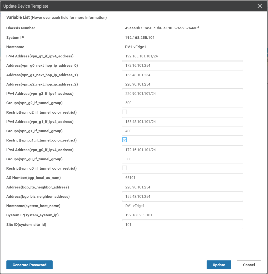
Configure the tunnel groups for each VPN Interface:
Push the configuration to the vEdge1, vEdge2, and DC1-vEdge1:
- Check the
restrictbox forbiz-internet - Set group accordingly for mpls, lte, and biz-internet.
Let’s see the BFD connections among three devices:
DV1-vEdge1# show bfd sessions
                                      SOURCE TLOC      REMOTE TLOC                                      DST PUBLIC                      DST PUBLIC         DETECT      TX
SYSTEM IP        SITE ID  STATE       COLOR            COLOR            SOURCE IP                       IP                              PORT        ENCAP  MULTIPLIER  INTERVAL(msec) UPTIME          TRANSITIONS
-------------------------------------------------------------------------------------------------------------------------------------------------------------------------------------------------------------
192.168.255.1    1        up          biz-internet     biz-internet     155.48.101.101                  155.48.1.1                      12346       ipsec  7           1000           0:00:06:57      1
192.168.255.1    1        up          mpls             mpls             172.16.101.101                  172.16.1.1                      12406       ipsec  7           1000           0:00:06:57      1
192.168.255.1    1        up          mpls             lte              172.16.101.101                  220.90.1.1                      12406       ipsec  7           1000           0:00:06:57      0
192.168.255.1    1        up          lte              mpls             220.90.101.101                  172.16.1.1                      12406       ipsec  7           1000           0:00:06:57      0
192.168.255.1    1        up          lte              lte              220.90.101.101                  220.90.1.1                      12406       ipsec  7           1000           0:00:06:57      1
192.168.255.2    2        up          biz-internet     biz-internet     155.48.101.101                  155.48.2.2                      12346       ipsec  7           1000           0:00:10:15      1
192.168.255.2    2        up          mpls             mpls             172.16.101.101                  172.16.2.2                      12426       ipsec  7           1000           0:00:19:30      0
192.168.255.2    2        up          mpls             lte              172.16.101.101                  220.90.2.2                      12426       ipsec  7           1000           0:00:10:15      0
192.168.255.2    2        up          lte              mpls             220.90.101.101                  172.16.2.2                      12426       ipsec  7           1000           0:00:10:14      0
192.168.255.2    2        up          lte              lte              220.90.101.101                  220.90.2.2                      12426       ipsec  7           1000           0:00:19:28      0


vEdge1# show bfd sessions
                                      SOURCE TLOC      REMOTE TLOC                                      DST PUBLIC                      DST PUBLIC         DETECT      TX
SYSTEM IP        SITE ID  STATE       COLOR            COLOR            SOURCE IP                       IP                              PORT        ENCAP  MULTIPLIER  INTERVAL(msec) UPTIME          TRANSITIONS
-------------------------------------------------------------------------------------------------------------------------------------------------------------------------------------------------------------
192.168.255.2    2        up          biz-internet     biz-internet     155.48.1.1                      155.48.2.2                      12346       ipsec  7           1000           0:00:00:17      1
192.168.255.2    2        up          mpls             mpls             172.16.1.1                      172.16.2.2                      12426       ipsec  7           1000           0:00:00:17      1
192.168.255.2    2        up          mpls             lte              172.16.1.1                      220.90.2.2                      12426       ipsec  7           1000           0:00:00:17      2
192.168.255.2    2        up          lte              mpls             220.90.1.1                      172.16.2.2                      12426       ipsec  7           1000           0:00:00:17      0
192.168.255.2    2        up          lte              lte              220.90.1.1                      220.90.2.2                      12426       ipsec  7           1000           0:00:00:17      1
192.168.255.101  101      up          biz-internet     biz-internet     155.48.1.1                      155.48.101.101                  12366       ipsec  7           1000           0:00:00:17      1
192.168.255.101  101      up          mpls             mpls             172.16.1.1                      172.16.101.101                  12366       ipsec  7           1000           0:00:00:17      1
192.168.255.101  101      up          mpls             lte              172.16.1.1                      220.90.101.101                  12366       ipsec  7           1000           0:00:00:17      0
192.168.255.101  101      up          lte              mpls             220.90.1.1                      172.16.101.101                  12366       ipsec  7           1000           0:00:00:17      0
192.168.255.101  101      up          lte              lte              220.90.1.1                      220.90.101.101                  12366       ipsec  7           1000           0:00:00:17      1


vEdge2# show bfd sessions
                                      SOURCE TLOC      REMOTE TLOC                                      DST PUBLIC                      DST PUBLIC         DETECT      TX
SYSTEM IP        SITE ID  STATE       COLOR            COLOR            SOURCE IP                       IP                              PORT        ENCAP  MULTIPLIER  INTERVAL(msec) UPTIME          TRANSITIONS
-------------------------------------------------------------------------------------------------------------------------------------------------------------------------------------------------------------
192.168.255.1    1        up          biz-internet     biz-internet     155.48.2.2                      155.48.1.1                      12346       ipsec  7           1000           0:00:08:06      1
192.168.255.1    1        up          mpls             mpls             172.16.2.2                      172.16.1.1                      12406       ipsec  7           1000           0:00:08:06      1
192.168.255.1    1        up          mpls             lte              172.16.2.2                      220.90.1.1                      12406       ipsec  7           1000           0:00:08:06      2
192.168.255.1    1        up          lte              mpls             220.90.2.2                      172.16.1.1                      12406       ipsec  7           1000           0:00:08:06      0
192.168.255.1    1        up          lte              lte              220.90.2.2                      220.90.1.1                      12406       ipsec  7           1000           0:00:08:06      1
192.168.255.101  101      up          biz-internet     biz-internet     155.48.2.2                      155.48.101.101                  12366       ipsec  7           1000           0:00:11:25      1
192.168.255.101  101      up          mpls             mpls             172.16.2.2                      172.16.101.101                  12366       ipsec  7           1000           0:00:20:40      0
192.168.255.101  101      up          mpls             lte              172.16.2.2                      220.90.101.101                  12366       ipsec  7           1000           0:00:11:25      0
192.168.255.101  101      up          lte              mpls             220.90.2.2                      172.16.101.101                  12366       ipsec  7           1000           0:00:11:24      0
192.168.255.101  101      up          lte              lte              220.90.2.2                      220.90.101.101                  12366       ipsec  7           1000           0:00:20:39      0
4. Conclusion
This post is served as a record for my learning process of how to create, attach device templates to WAN Edge devices for BGP configuration. From time to time, whenever I forget something, I can always refer to this for specific details. If anyone finds it useful, it’s my pleasure!
Comments